First steps
This section uses a fairly simple behavior to illustrate key concepts: application behavior, state machine modeling, and visual modeling language. We also show how the application behavior can be connected to the rest of the application concerns — e.g., displaying screens, fetching remote data.
Do not worry if there are new words whose meaning is not entirely clear from the get go. The remainder of the tutorials will explore the concepts more in details. What follows will give you a preliminary feel of the API.
Counter application behavior
Let’s implement the simplest behavior we can think of: a counter. The behavior of an application is the mapping of the reactions of the application to occurring events. Here, there is only one event: the user click on the increment button. The behavior of the counter application is to display an incremented counter every time the user clicks the incrementing button. In summary, the event/reaction mapping is as follows:
| Event | Reaction |
|---|---|
| click on button | render screen with incremented counter |
Counter application modeling
A Kingly state machine is a function that computes the reactions (termed as commands) corresponding to the event (mschine input) it is passed as parameter. In pseudocode:
// fsm is a Kingly state machine
const commands = fsm(event);
A Kingly state machine (fsm) has two encapsulated pieces of state that are updated as events are processed: the control state and the extended state. To each control state is associated a different way to compute the reaction to events. Any such computation use the extended state of the machine and the event to compute commands, after updating the machine state. In pseudocode, it would look as follows:
The control state takes its name from the fact that it determines the control flow (branch) of the machine computations. A state machine thus partitions one stateful computation into several. The challenge of modeling an application behavior is to identify those control states that determine the reaction to events in ways that are both economical and natural.
let controlState = ...;
let extendedState= ...;

function fsm(event){
  if (controlState === CS1){
    return someComputation(event)
  }
  if (controlState === CS2){
    return anotherComputation(event)
  }
}

// Updates state in closure
function someComputation(event){...}

// Updates state in closure
function anotherComputation(event){...}
Our counter application admits only one event. There is only one way to compute the corresponding command. A single control state is thus enough. The extended state of the machine can host the counter value. The counter application behavior can thus be represented with a state machine that:
- has a single Counting control state;
- encapsulates the counter value in its extended state (initial value 0); and
- on receiving a click event, updates its internal state (identical control state, incremented extended state), and returns a render command parameterized by the incremented counter value.
In pseudocode:
let controlState = Counting;
let extendedState= 0;

function fsm(event){
  if (controlState === Counting){
    return incrementCounterAndRender(event)
  }
}

// Updates state in closure
function incrementCounterAndRender(event){
  extendedState++;
  return [{command: RENDER, params: extendedState}]
}
State machines can be visually represented by a graph that links together its control states. That is, the nodes of the graph map to the control states of the machine. The counter behavior may for instance be visualized as follows:
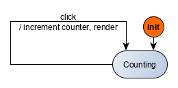
The previous graph illustrates the event [guard] / actions notation that is used for edges in the graph editor and throughout all the tutorials. As there are no guards here, the syntax shortens to event / actions. An edge links an origin node to a target node if and only if event results in the machine computing something — we say that the machine accepts the event. The target node of the edge is the control state that the machine ends in. Here, the machine processing the click event does not lead it to change its control state. The edge in the previous graph thus both originates and returns to the Counting control state.
Alright. So we have our behavior (the mapping event/reaction), the machine that models that behavior (the stateful function specified by the mapping), the graph visualization of the machine. We still have to draw the application screen. A Kingly machine merely computes commands, it does not execute commands (i.e., it does not perform effects besides updating its own state). For a fully running application, we thus have to write the procedures that execute the computed commands. Our implementation is as follows:
Logs are activated by passing a console object in settings ({ debug: { console }}). We recommend to activate logs in the early stages of your learning and as a debugging tool.
Note how in the previous code events are passed as inputs to the machine, leading to commands being output and then executed. In this simple case, we opted for direct DOM updates to render the counter application screen.
Now open the console in the playground and have a look at the logs. Click the button once, and have another look at the logs. Formatting aside, you should see messages that allow following the machine computation step by step:
- The first event (
init) is an internal event that is sent to put the machine in its initial state. That event is sent when the machine is created. - The second event (
clicked) corresponds to your button click. - Action factories are functions that compute actions. Actions are of two kinds: updates to the machine extended state, and commands output by the machine.
ACTION_IDENTITYstands for an action factory that produces no actions, leaving the state of the machine intact, and producing no commands.
send event ▶{init: Object}

found event handler!
WHEN EVENT init ▶{count: 0}
IN STATE -nok-
CASE: unguarded transition
THEN: we execute the action factory ACTION_IDENTITY
left state -nok-
AND TRANSITION TO STATE -counting-
ENTERING NEXT STATE: -counting-
with extended state: ▶{count: 0}

send event ▶{clicked: undefined}

found event handler!
WHEN EVENT clicked undefined
IN STATE -counting-
CASE: unguarded transition
THEN: we execute the action factory incCounterAndDisplay
left state -counting-
AND TRANSITION TO STATE -counting-
ENTERING NEXT STATE: -counting-
with extended state: ▶{count: 1}

OUTPUTS: ▶(1) [Object]
         ▶0: Object
            command: "render"
params: 1“Sometimes the elegant implementation is a function. Not a method. Not a class. Not a framework. Just a function.” – John Carmack
The code playground illustrates a key feature of Kingly’s state machines. They are normal, plain, standard JavaScript functions! You could replace the fsm created by Kingly by a function controller fulfilling the same specifications:
let count=0;

function controller(event){
  const eventName = Object.keys(event)[0];
  if (eventName === 'clicked'){
    count++;
    return [{command: "render", params: count}]
  }

  return void 0
}
This is it! You don’t need a PhD to understand Kingly state machines. You write stateful functions like controller all the time when implementing event handlers. Writing such controller functions as state machines allows you to split the controller computation into smaller, simpler computations. State machines have a visual representation that emphasizes computation logic (the control flow) over implementation details (the actual state updates and commands). This will get increasingly clear as we introduce more complex applications in the remainder of the tutorials.
What we learned
This is the very short story about state machines used for modeling the behavior of user interfaces. The application behavior is the set of its reactions to events. A Kingly state machine works as a functional, stateful controller that transforms events into commands that encode but do not execute the reactions. The application is implemented by composition of three parts: instantiation of event listeners, computation of the reaction (commands) to events, and execution of the reactions. To execute the command that renders a screen, you can use any UI library you fancy, or just plain JavaScript — as we did in this example.
States machines can be visually represented by a graph whose nodes are the machine’s control states. The edges of that graph are associated with the control state a machine is in when receiving an event, the new control state it ends in as a result, and the computation it performs (event [guards] / actions notation for the edge label).
Let’s move to a more interesting example: a password meter.